MIDI & Music Synthesis: A Quick Tutorial
Introduction
Composers and musicians have been using Musical Instrument Digital Interface or MIDI since 1982. It is a widely accepted protocol because of its efficiency in the management of musical performance-related information. MIDI is also very popular among computer scientists, especially those who are focused on the development of sound-producing computer applications. Advances in information and communications technology have paved the way for the creation of standards for the generation of MIDI-based sounds. This article will offer an insight into these standards and best practices to give MIDI users a better understanding of how the system can work for them.
MIDI vs. Digitized Audio
The initial purpose of the MIDI protocol was to provide a means for connecting different synthesizers. Today, the protocol aims to replace conventional media for delivering high-fidelity sounds. MIDI can also supplement digitized sounds in multimedia applications and games.
The strength of the MIDI protocol is its data carrying capabilities. It doesn’t convey the whole audio data. Instead, MIDI contains only codes or messages that a synthesizer needs and translates into sounds. This unique characteristic gives MIDI several advantages over conventional digitized audio formats.
MIDI files can be 100 times smaller than .WAV files, having the same amount of audio playtime. This protocol also maximizes the bandwidth needed by computers to communicate with sound-generating peripherals. The code-only nature of MIDI also allows users to edit or modify the different elements of the sampled audio.
MIDI Basics
The main purpose of the MIDI protocol is to deliver music information-containing electronic data in a standardized and more efficient manner. A synthesizer receives and processes these MIDI messages and converts them into actual sounds.
A typical MIDI device will have 3 basic connectors: IN, THRU, and OUT. Data streams can start from MIDI controllers or MIDI sequencers. In general, MIDI controllers are found in certain musical instruments. The controller translates the music performance into data stream. A MIDI sequencer captures, stores, combines, edits, and replays data sequences. Data output from both MIDI sequencers and controllers get transmitted through the OUT port of the MIDI device.
MIDI sound modules or sound generators receive the MIDI data streams through the IN port. These MIDI components then play the sounds. There are also MIDI keyboards that have both integrated controller and sound module. In such instruments, there is a local control mechanism that allows users to turn the functionality ON and OFF.
Each physical MIDI channel has 16 logical channels. A MIDI controller can transmit data streams on any of these 16 channels. A MIDI sound module can receive data streams from a specific MIDI channel.
Data streams from the IN port of a controller can be resent to the THRU port of the same controller. It is possible to daisy-chain several sound modules by connecting a device’s THRU output to the IN port of another device.
The MIDI protocol is also present in personal computers. Examples of software that can contain this protocol include MIDI sequencers, music scoring, games, educational packages, multimedia presentation packages, and reference libraries. These applications send MIDI messages to a MIDI interface card, which then converts the MIDI messages into serial data.
MIDI systems for the PC can come in different configurations. There are PC cards that already integrate a MIDI sound module and a MIDI interface. This is the standard specification for multimedia PCs or MPCs. There are also PCs that still use FM synthesizers in their sound cards. More advanced systems already integrate a wavetable synthesizer module on the mainboard. Other systems incorporate this system as a card option.
MIDI Messages
Each MIDI message contains 8-bit-status bytes and one to two data bytes. MIDI messages come in different types. The highest levels of MIDI messages are the System Message (SysM) and the Channel Message (CM). Channel messages are channel-specific and include a status byte for the channel number. System messages don’t require the inclusion of a channel number as a status byte. These are also not specific to any channel.
There are two subtypes of CMs: Mode Messages (MM) and Channel Voice Messages (CVM). Typical MIDI data streams contain CVMs that carry data about musical performance. On the other hand, MMs allow MIDI receiving units to process and respond to the CVMs.
- Channel Voice Messages
These messages contain information about musical performance. They include the following messages.
- Note On/Note Off/Velocity
A MIDI keyboard sends to the MIDI OUT port a Note On message through any of the 16 logical channels of the MIDI system. The Note On message includes a status byte that contains the selected channel number and two data bytes. One data byte codes for a key number. Another data byte contains information about velocity or the pressure exerted on the keyboard key.
The key number allows the receiving synthesizer to choose the right note to play. The velocity controls the note’s amplitude. Releasing the keyboard key signals, the MIDI controller to transmit a Note Off message.
- Aftertouch
There are MIDI keyboards that can read pressure information – or aftertouch – whenever the keys are depressed. This allows for the control of some aspects of sound production. Some keyboards can send Polyphonic Key Pressure messages if each key has a pressure sensor. However, most MIDI keyboards only have a single pressure level across the board.
- Pitch Bend
This message modifies a sound’s pitch in response to pitch bend wheel position changes. Each pitch bend message contains 2 data bytes that code for a specific bitch bend value, allowing the pitch bend wheel to move continuously.
- Program Change
This type of CVM specifies the instrument needed to play a sound on a specific channel. It contains one data byte that corresponds to the program number.
- Control Change
These messages control different synthesizer functions and affect only the channel number specified in the CVM’s status byte. There are also two data bytes that follow the status byte. One data byte indicates the controller number, while the other indicates the control value. The controller number specifies the synthesizer function that the CVM will control.
- Bank Select
There are two controller numbers for Bank Select: 0 and 32. Bank select works with the Program Change (PC) message in increasing the number of instrument sounds that can be specified. Each PC message can code for 128 different program numbers. Adding instrument sounds results in the generation of 16,384 banks, each containing 128 sounds.
- RPN/NRPN
Registered and Non-registered Parameter Numbers allow for the editing of sound patches as well as other data. RPNs allow for the control of the synthesizer’s master tuning and the sensitivity of the pitch bend. NRPNs are parameters that do not have specific assigned functions. Manufacturers can assign functions to these numbers as they see fit.
- Channel Mode Messages
Different Channel Mode messages allow the synthesizer to perform different functions. Controller 121 resets all controllers, while Controller 122 controls Local Control. Controllers 124 to 127 allow access to the synthesizer’s Omni, Mono, and Poly Mode functions.
The Omni Mode ON allows the synthesizer to receive all messages from all channels. The Omni Mode OFF permits only messages coming from a single channel. The Poly Mode allows for the playing of Note On message polyphonically. This results in the simultaneous playing of multiple notes. The Mono Mode assigns a single voice for every channel. Many synthesizers come with an Omni on/Poly Mode as default.
MIDI instruments always have a Basic Channel that allows the instrument to receive MIDI Mode messages.
- System Messages
There are three subtypes of system messages.
- System Common Messages
These messages synchronize the different components of the system, including the MIDI equipment, videotape machines, audio devices, and others. It includes instructions for song selection, tune request, MTC quarter frame, end-of-exclusive, and song position pointer.
- System Real Time Messages
These messages synchronize the different clock-based components of the MIDI system, including drum machines and sequencers. The messages include information about system reset, timing clock, active sensing, start, stop, and continue.
- System Exclusive Messages
These messages transfer data bytes in manufacturer referenced and specified format. It can also contain sample data and patch parameters. There are also System Exclusive identification numbers that work only for special protocols, such as the MIDI Machine Control, MIDI Show Control, and MIDI Sample Dump Standard.
- Running Status
This is a technique that allows for the reduction of the volume of data that gets transmitted in the data stream. Without the Running Status, every single note can generate a string of Note on and Note Off messages. This can increase the amount of data. With the Running Status, the system only sends a status byte if the message is a different message type from the same channel. Similar message types no longer require their respective status bytes. They only require data bytes.
MIDI Sequencers and Standard MIDI Files
MIDI synthesizers receive and process MIDI messages in real time, allowing it to play the right sound as coded by the Note On message. A Note Off message will command the synthesizer to turn off the note. Real-time applications don’t require timing information in the MIDI messages. Only when MIDI data are stored and/or edited will the messages require time-stamping.
Sequencers allow for the storage and editing of a MIDI data file. Multimedia presentation software and music scoring packages can also use time-stamped MIDI data files for sharing across multiple platforms. Currently, there are three standard MIDI file formats. Format 0 contains single track MIDI data. Format 1 contains a collection of MIDI data tracks. Format 2 stores MIDI data with Independent patterns. In general, Format 2 is not intended for musical applications.
Synthesizer Basics
- Polyphony
This reflects the synthesizer’s ability to play multiple notes simultaneously. The number of voices or notes that the synthesizer can play at the same time denotes the device’s polyphony.
- Sounds
A synthesizer can produce different sounds, each with an assigned program number. Program numbers are also called timbres, algorithms, or patches. A Program Change message allows the synthesizer to change an instrument sound on a channel with a different instrument sound.
- Multitimbral Mode
There are synthesizers that can produce at least two different instrument sounds at the same time. For example, a synthesizer is said to be multitimbral if it can produce the sounds of an acoustic bass and a piano at the same time. Add to this its capability of playing five different notes in a simultaneous manner. The effect is that of a sound produced by an orchestra or a band.
The General MIDI (GM) System
The General MIDI System allows the establishment of relationship standards between specific sounds and patch numbers. It allowed a MIDI sequence to produce the same sounds even when played using different synthesizers.
The system defines how a General MIDI instrument should have its patch map designed (Sound Set), the actual mapping of the percussion sounds that will correspond to note numbers (Percussion Map), and the MIDI message types and number of voices that the instrument can play (Performance Capabilities).
Chromatic instrument sounds are assigned to channels 1 to 9 as well as channels 11 to 16. Key-based percussion instrument sounds get channel 10. There are also program numbers that correspond to related instrument sounds. For example, piano-related sounds are assigned program numbers 1 to 8, while percussion-related sounds are assigned program numbers 9 to 16.
Synthesis Technology: FM and Wavetable
Wavetable synthesis and frequency modulation at the two most common technologies used in synthesizers to create sounds. Frequency modulation sound synthesis techniques are useful when it comes to the creation of new synthesized sounds. Unfortunately, FM technology is less accurate when it comes to synthesized sound recreation. A better approach for such a purpose is wavetable synthesis.
Wavetable synthesis techniques are also known as digital sample-based techniques. These techniques allow for the more efficient digital storage of high-quality audio sample. Digital sampling systems also allow the replaying of these digitally-stored sounds on demand.
Wavetable synthesis often uses the following techniques.
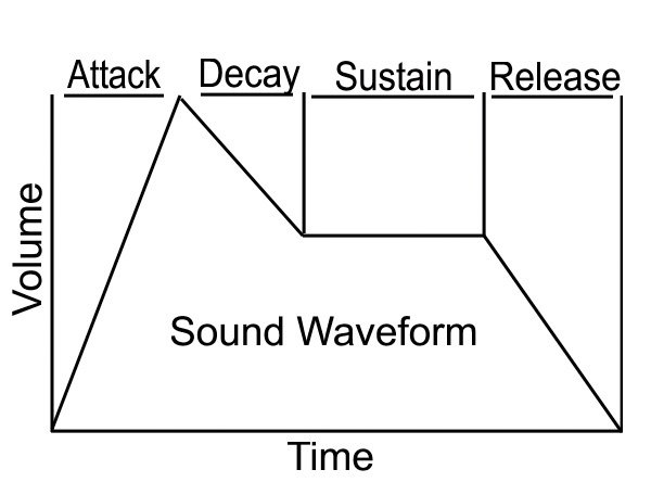
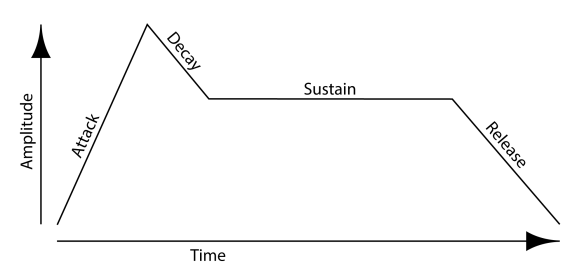
- Looping and Envelope Generation
Looping allows a segment of sampled sound to be used for the sustain portion of the recording during playback. This results in a signal with a more constant amplitude. An envelope that consists of a sound’s attack, decay, sustain, and release segments can also be generated and applied to the looped waveform. Looping allows the reduction of the sustain portion’s storage requirements.
- Loop Length
The number of sampled sounds determines the length of the loop. It is equivalent to the number of periods that correspond to the pitch of the played sound.
- One-shot Sounds
There are sounds that cannot be looped because they are either of short duration or are very dynamic. These sounds are called one-shot sounds.
- Sample Editing and Processing
Editing and processing is necessary in the preparation of sampled sounds. These processes are also crucial in ensuring the compatibility of loop segment endpoints. Additional processing can also be executed to compress a sound’s dynamic range. This improves signal-to-noise ratio, while also conserving sample range.
- Sample Data Compression
Compression techniques improve the ratio between signal and quantizing noise. In general, data compression techniques allow for the more efficient reduction of a sound sample’s dynamic range to improve storage.
- Pitch Shifting
Pitch shifting helps reduce the requirements of sample memory. It allows the generation of several different notes using only a single instrument sound sample. Pitch shifting requires access to the sample data stored in the sample memory.
- Interpolation
This technique allows for the use of a more concrete sample value when the value of the data sample includes a fraction. Simple systems use a sample value that is nearest the available value. For example, if the sample value is 1-1/2, then the nearest available whole number value is 2. Other systems use more sophisticated interpolation systems.
- Oversampling
One way to improve distortion is by using oversampling techniques. The downside to using such a technique is an unwanted increase in the requirements of the sample memory. Linear interpolation can help mitigate such effects.
- Splits
Velocity splitting and key splitting are important wavetable synthesis techniques to enhance musical performance. Key splits refer to the different range of notes that an instrument keyboard can play. Each range will have a different sampled sound. Velocity splits, on the other hand, refer to the clustering of different note amplitudes or velocities. Each of these groupings will have its own sample.
- Aliasing Noise
Pitch shifting can produce changes in the timbre of sounds. Resampling can also introduce aliasing noise, which can have an impact on the effectiveness of pitch shifting techniques. Low-pass filtering and oversampling can negate the unwanted effects of such noise.
- LFOs for Tremolo and Vibrato
Low-frequency oscillators simulate vibrato and tremolo effects. The addition of an envelope generator can also help mimic the tendency of natural tremolo and vibrato effects to become stronger with sustain.
- Layering
This technique allows for the generation of very rich sounds by adding multiple sounds for each note that the synthesizer plays. Layering can also improve the creation of instrument patches using only a limited set of sound samples.
- Digital Filtering
Filtering not only negates aliasing noise. It can also improve the quality of instrument sound by improving the sound’s timbre. Digital filtering can also smoothen the transitions between key-based split sound samples, while also adjusting the spectrum of the output frequency of the sample.
The PC to MIDI Connection
A PC to MIDI interface device is necessary to use the MIDI platform on a computer. The interface can come in the form of an add-in card, a serial port interface, or a parallel port interface. The most common type of PC-to-MIDI connection is the serial interface.
The MIDI interface converts data bytes between the serial MIDI data format and the PC data bus. More advanced MIDI interfaces can generate MIDI timing data, message filtering, data buffering, and external synchronization, among others.
- PC Compatibility Issues
The effectiveness of a MIDI application for PCs is dependent on two things. The application must be compatible with both the type of MIDI interface and the type of MIDI synthesizer used.
- MS-DOS Applications
Sequencing applications, some games, and music scoring packages are the typical MS-DOS applications that are compatible with a MIDI synthesizer. As for the MIDI interface, a computer only needs an MPU-401 standard interface or a similar interface to run the applications.
Multimedia PC (MPC) Systems
Multimedia PC systems started in 1991 with the introduction of the Microsoft Windows 3.1 OS. The standards call for a computer system with the capability for recording and playing digital audio. It also allows for the mixing of sounds and the synthesis of music.
Current MPC standards call for two different types of synthesizers that strike a balance between performance and affordability. A Base Multitimbral Synthesizer should be able to play 2 percussive notes, 6 melodic notes, 2 percussive timbres, and 3 melodic timbres. An Extended Multitimbral Synthesizer can play 8 each of percussive notes and percussive timbres, 9 melodic timbres, and 16 melodic notes.
MPC systems also have authoring standards when it comes to MIDI compositions. Each MIDI file should have a separate arrangement for a Base and an Extended synthesizer. Unfortunately, this became problematic for GM synthesizers. Microsoft addressed this issue by ditching the dual-format for a GM model in future Windows releases. The problem is that there are still MIDI data that are authored for the dual-format model. The only way to address this is by using a Windows MIDI Mapper.
Microsoft Windows Configuration
The compatibility of a MIDI device to a Windows application is dependent on the availability of an appropriate driver. Drivers for both MIDI synthesizers and interfaces should be installed in the Windows system for these devices to run efficiently.
A MIDI Mapper applet helps in the routing of digital information from a MIDI-using application to the correct device driver. Users can configure the Mapper to filter or translate MIDI data as it gets conveyed from the program to the device driver. The MIDI Mapper contains setups, key maps, and patch maps that can help define the specific function to be performed by the Mapper.
Summary
The MIDI system is an efficient protocol for transmitting critical data on musical performance, while also allowing different applications to share MIDI data. It also provides better editing capabilities on the go and more efficient storage. Multimedia applications and sound generation platforms can always rely on advances in MIDI-based synthesizers, including more innovative applications and the continuing development of wavetable synthesis.
Other MIDI Guides: